 In this tutorial, you will learn how to install a motorcycle gear indicator in a 2004 Yamaha Fazer.
Have you ever tried to engage 7th gear? Tired of trying it so many times, and riding in not so appropriate gears for the speed, I decided to install a gear indicator on my 2006 Yamaha Fazer ABS.
I bought an Acumen gear indicator on ebay (around 80 € new). I chose this brand because it has a blue display, and I think it looks nicer, since it is similar to the Fazer speedometer.
In a gearbox, the ratio between rpm’s and speed is constant for each gear. The gear indicator calculates the value of the actual constant, and therefore knows which gear is engaged. To perform this calculation, the gear indicator needs to «read» the rpm and speed signal from the motorbike.
In most modern motorbikes the information sent to the speedometer is embedded within a protocol, so it is hard to «read» that info from there. It is much easier to «hijack» that info from the cables that go to the ECU.
![]() Disclaimer: Installation of a gear indicator requires soldering and disassembling parts of the motorbike. It is only recommended for people with knowledge and experience in mechanics and electronics. This document shows the steps that I took to install a gear indicator on my motorbike. I take no responsibility for any damage suffered for the use or misuse of this information.
Disclaimer: Installation of a gear indicator requires soldering and disassembling parts of the motorbike. It is only recommended for people with knowledge and experience in mechanics and electronics. This document shows the steps that I took to install a gear indicator on my motorbike. I take no responsibility for any damage suffered for the use or misuse of this information.
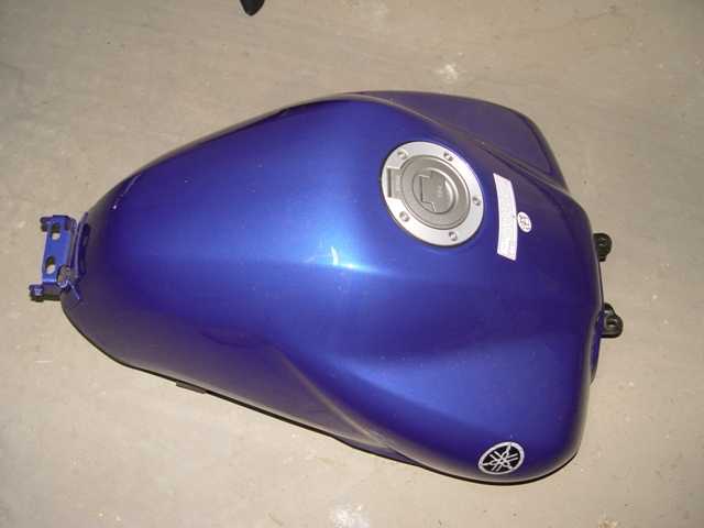
1. Disassembling the gas tank
The ECU is under the gas tank, so it is necessary to disassemble it to gain access to the ECU.
Although the right way to disassemble the gas tank is emptying it (BTW it is the way recommended by Yamaha), if you are careful enough you can do it with gas in the tank. Obviously, the fewer gas you have inside the tank, the better, since the gas tank will be lighter.
To gain access to the ECU, the gas tank can be disassembled completely, or it can pivot around the hinge and be held in a vertical position using some ropes. In the cowled version, the gas tank can not pivot without disassembling the front cowling inner panels.
I think it is safer to unscrew the gas tank and disassemble it completely.
First of all, the two allen bolts shown in the picture have to be unscrewed:
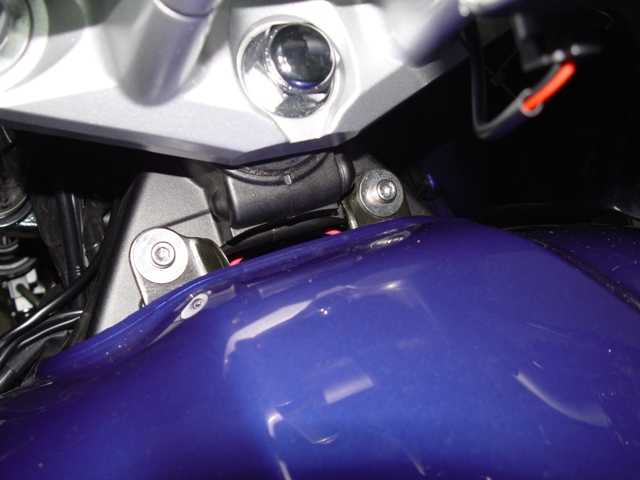
Since I have the cowled version, I decided to unscrew the hinge, so that I could move the gas tank slightly and avoid disassembling the inner cowling panels.
Once I got the gas tank over the cowling panels, I screwed the hinge again to reduce the risk of dropping the gas tank.
![]() Caution: Be extremely careful to avoid dropping the gas tank to the floor or over a hand. I strongly recommend you to use a wedge.
Caution: Be extremely careful to avoid dropping the gas tank to the floor or over a hand. I strongly recommend you to use a wedge.
To continue disassembling the gas tank, I had to disassemble the following parts:
- Two rubber hoses:

- Two electric connectors (no picture)
- The fuel hose and its plastic clip:

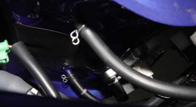
Once the black plastic clip is removed, pressing the two gray little «buttons» will release the hose and it can be pulled away. This was the only hose where I had a small gas leakage, so I recommend to have a cloth at hand.
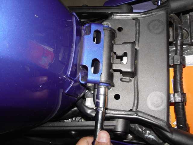
Now, the hinge can be unscrewed again. The gas tank should be set on a horizontal surface:
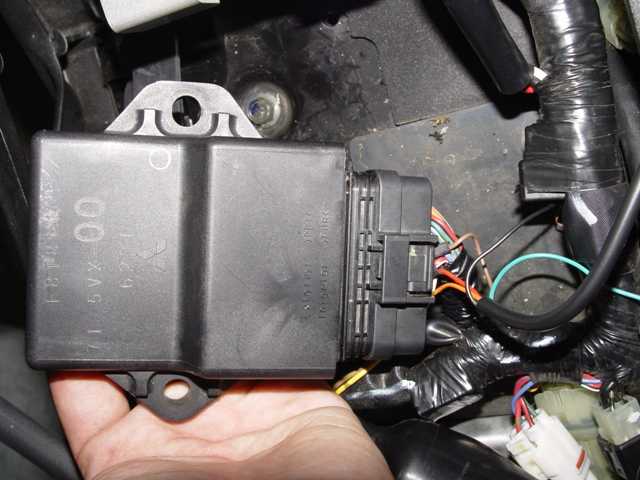
2. ECU
I disassembled much more than was needed, so don’t worry if these pictures don’t look much like your motorbike.
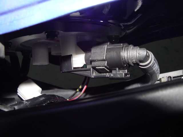
The ECU is the black box that is close to the gas tank hinge. Here you have a picture so that you know what it looks like (unscrewing it is not needed):
The ECU connector must be unplugged. This connector is pretty hermetic, to avoid humidity and dust entering the ECU.
Once the connector is unplugged, a small white lines on the sides of the connector. By pressing those white lines, you will lock/unlock the cables:
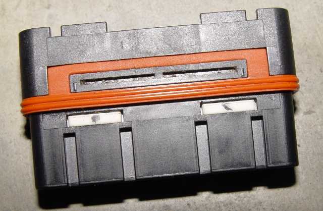
If the white lines are pressed on one side, the cables can be released just by pulling of them. If the white line on the other side is pressed, the cables will be locked and can not be pulled away.
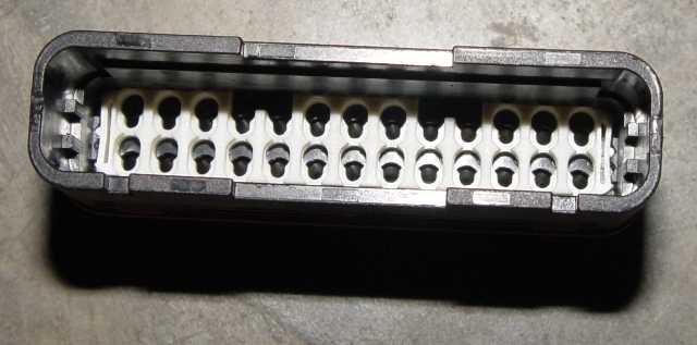
You don’t need to take all the cables away (just three of them). As I said, I disassembled much more than was needed, and it was a real pain to assemble it again. This is a pinout of the connector:
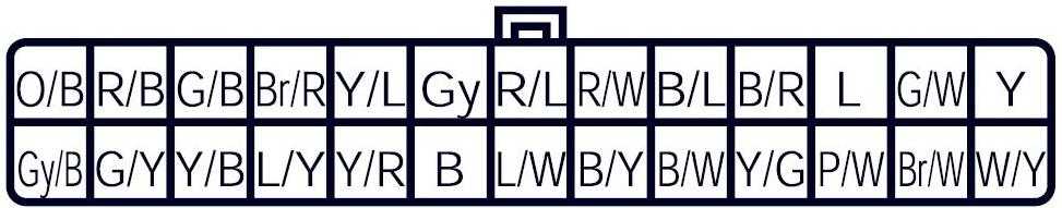
| Code in connector | Color in ECU | Color in Acumen Digi | Function |
| Gy | Gray | Brown | RPM |
| R/W | Red / White | Red | Positive (+) |
| W/Y | White / Yellow | Orange | Speed |
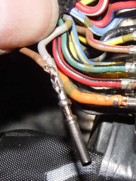
These are the three cables that need to be «hijacked» from the ECU. Once the cables (with their terminals) are outside the connector, the cables of the gear indicator must be soldered to the terminals according to the previous table. The solder has to be thin enough so that the terminal will fit into the connector again.
In the next picture you can see the solder between gray and brown cables (rpm’s):
Once the three solders are done, the terminals need to be introduced back again into their place, and the white line of the connector must be pressed to lock the cables again. Sometimes this can be a little tricky, because if any of the terminals is not fully inserted into the connector the white bar will not move. When this happens, you can look through the opposite side of the connector and see which terminals are not fully inserted.
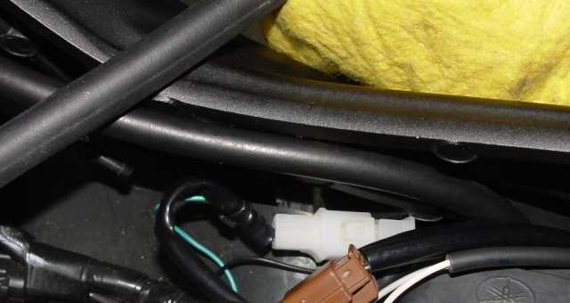
There is one cable from the gear indicator still not connected (the neutral indicator cable). This cable is not present in the ECU connector, so it has to be «hijacked» from somewhere else. This cable goes up along the right side of the motorbike and it is light blue (although it is inside a black cover). This cable has to be connected to the green cable of the gear indicator:
To program the gear indicator, I got the motorbike on the centerstand, chose the number of gears (six), and engaged each gear for a few seconds, so that the gear indicator could learn the ratio of each one.
Although the gear indicator manual says that in this model of motorbike the neutral indicator light (N) on the speedometer could remain always on (and recommends using a diode to fix this), in my motorbike that light worked as expected except for when the clutch lever was pressed, that the light would also glow.
I didn’t like this very much because if I stopped in a traffic light with a gear engaged and the clutch lever pressed, seeing the N light could trick me into thinking that neutral was indeed engaged, and I could release the clutch lever, stopping the motorbike engine.
I played around with a diode, connecting it to the green cable, but I couldn’t fix this problem. At the end, I decided to leave the green cable disconnected. With this configuration, the gear indicator worked as expected, although it never shows a N on the screen (although the N light indicator of the speedometer works fine).
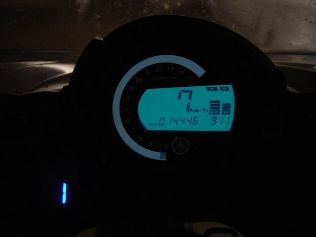
3. Final Results
Here you have the final results:

Hi, could you tell/send me all the pin function of the ECU?
Thank you.
I’ll send you a PM.
Hey man can you sent me the diagram for the 2005 Yamaha fz6
Hi, same question than Jaime Cosme, can i have all the pin function please ? Thanks
Hi,
you could get the diagram from this link.
thanks you very much !
Hi
I bought a datatool gear indicator but i cant find the wiring colors like they said in manual
They said to connect the gear shift indicator below the speedomether wires. You have any wiring diagrams about that wires ?
Thank you for your time
Hi Daniel,
on some motorbikes, the gear indicator can be connected directly to the wires that go into the speedometer.
But on the Yamaha FZ6 it doesn’t seem possible because most of the information shown on the speedometer is supplied by the ECU using just one wire.
I have uploaded the FZ6 wiring diagram. As you can see, number 34 is the speedometer, and the speed and rpm wires are not connected to the speedometer.
Hello,
I had problem with neutral light staying on even if I was in gear. So I went in my garage, took old cassette HU and i found there correct diode.
here is written for similar gear indicator like it is mine from china for 25$ and is the one without magnet sensors. This is the diode number 1N4148 and it looks like this and in ma head unit (smaller under big red one).
In manual on above link it says tut put it in gear indicator PCB instead of resistor R3 but I tried to put it between Gear indicator neutral sensor wire and the blue wire of neutral switch on my FZ6 ABS 2007, first did not worked, not even Gear indicator, but than I turned diode around and IT WORKS !!! (I firstly tried with the big red one diode but It was not work beacuse i think it is not right diode so the 1N4148 is the right one!
And great thing is that you could put it in between wires, not needed soldering gear indicator.
I think this will help allot of people, so if you can just spread info over the internet 🙂
Cheers
Thanks Lenart,
I think it can really help.
Hi, can you send me a copy of all the function of the pinout of ecu you have shown?it is the same as mine. thanks